Uml Timing Diagram Online Tool
Made with
Timing diagram
How To draw UML Timing Diagrams
UML Timing Diagram as special form of a sequence diagram is used to explore the behaviours of objects throughout a given period of time. The difference from sequence diagram is that the axes are reversed so the time is increased from left to right and the lifelines are shown in separate compartments arranged vertically.

Example 1. UML timing: library, template and example
ConceptDraw has examples and templates that helps you to start using software for drawing UML Diagrams. You can use the appropriate stencils of UML notation from UML Timing library with 15 objects.

Example 2. UML timing diagram
This example is created using ConceptDraw DIAGRAM diagramming and vector drawing software enhanced with Rapid UML solution from ConceptDraw Solution Park.

Example 3. Rapid UML solution
Rapid UML solution provides templates, examples and libraries of stencils for quick and easy drawing UML 2.4 timing diagram.
Use ConceptDraw DIAGRAM with UML Timing Diagram templates, samples and stencil library from Rapid UML solution to model how the objects of your system change their state or value over time, and how the timed events interact.
TEN RELATED HOW TO's:
Flowchart design. Flowchart symbols, shapes, stencils and icons →
When thinking about data visualization, one of the first tools that comes to mind is a flowchart design. You can find flowchart symbols, shapes, stencils and icons easily on the Internet, but it might take time to systematize this information. Nevertheless, once you start flowcharting, you'll love its simplicity and efficiency. This diagram consists from standard flowchart symbols, approved by ANSI (American National Standard Institute) for drawing flowcharts. A flowchart is a diagram that represents a step-by-step algorithm of any process, displaying the process stages as boxes that are connected with arrows. Flowchart design makes it clear and readable. Flowchart designed using ConceptDraw DIAGRAM flowchart software allows to make attractive and clear process presentation, it makes interpretation of the business process flow fresh and versatile. Great flowchart design view is a big advantage over the diagram created manually on a paper. 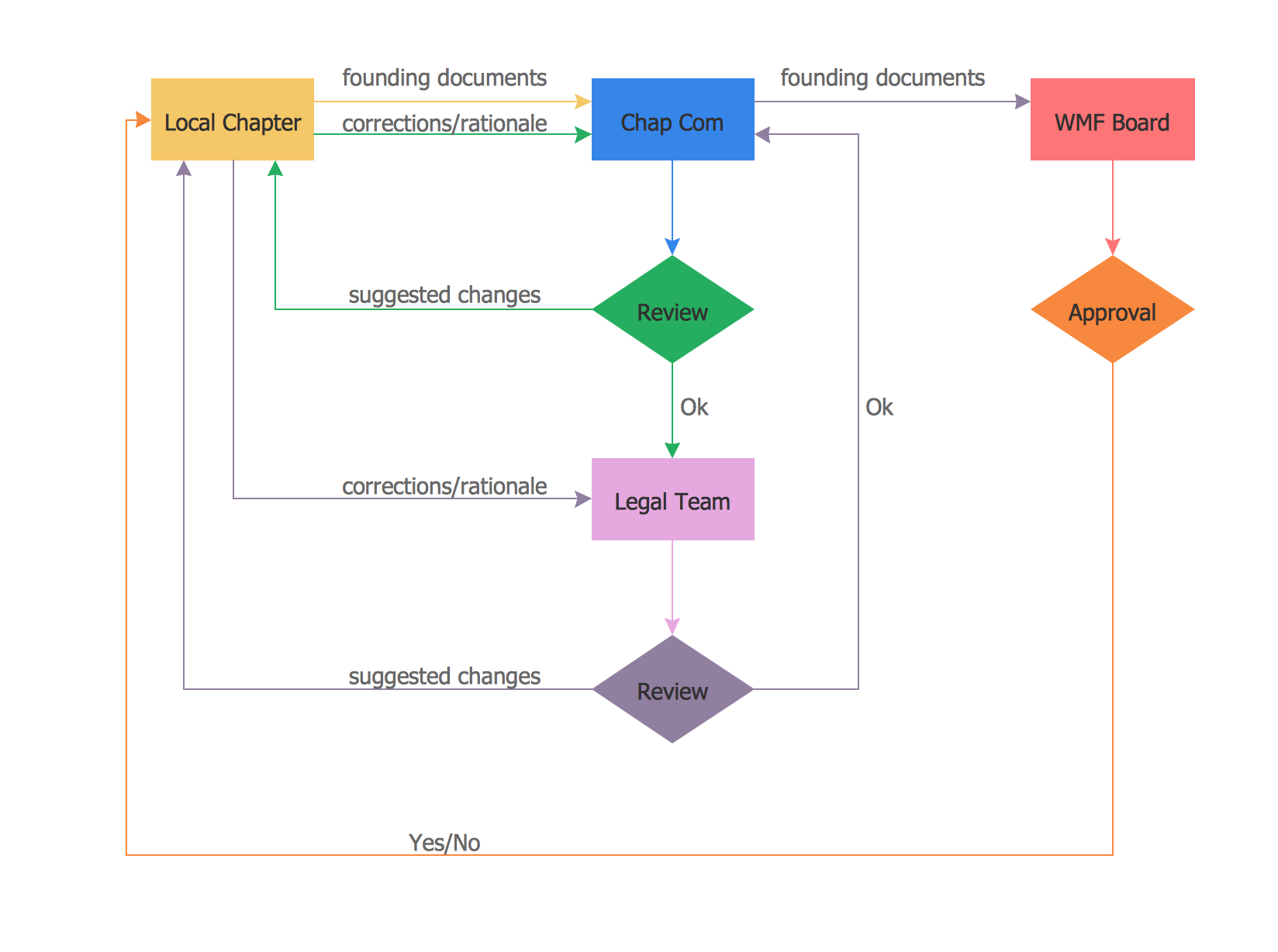
Picture: Flowchart design. Flowchart symbols, shapes, stencils and icons
Related Solution:
UML Collaboration Diagram. Design Elements →
UML Collaboration Diagram illustrates how components are wired together to larger components and software systems that shows the structure of arbitrarily complex systems. ConceptDraw has 393 vector stencils in the 13 libraries that helps you to start using software for designing your own UML Diagrams. You can use the appropriate stencils of UML notation from UML Collaboration library with 36 objects 
Picture: UML Collaboration Diagram. Design Elements
Related Solution:
How to create your UML Diagram →
The UML diagrams in this Solution are divided into three broad categories: Structure Diagrams; Behavior Diagrams; Interaction Diagrams. The 13 diagrams contained in the Rapid UML Solution offer an essential framework for systems analysts and software architects to create the diagrams they need to model processes from the conceptual level on through to project completion. 
Picture: How to create your UML Diagram
Related Solution:
Cafe Design →
Cafes and restaurants are the places for relax and recreation, so the most important is their design and atmosphere of comfort, harmony, and uniqueness. So Cafe Design requires great creativity and efforts from the designers. ConceptDraw DIAGRAM software extended with Cafe and Restaurant Floor Plan solution from the Building Plans area of ConceptDraw Solution Park is the most simple way of displaying your Cafe Design ideas and plans first on the computer screen, and then on the paper. 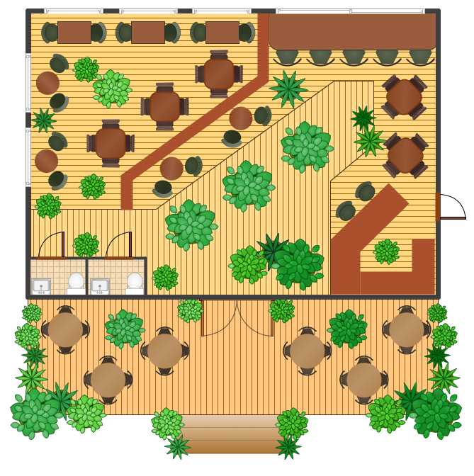
Picture: Cafe Design
Related Solution:
How To Create CCTV Network Diagram →
Closed-circuit television (CCTV) uses cameras and monitors to carry out video surveillance. Unlike broadcast television this system has only local signal. It is a feature of almost every video camera, yet CCTV is mainly a system for visual control of certain areas such as banks, airports, supermarkets, and other places for security reasons. Developing and installing CCTV system is a time-consuming process. It also requires certain knowledge and skills. ConceptDraw is a solution of setting video cameras rationally. You can achieve two aims at once: CCTV Design Tool saves your time and your money and helps you make professional video surveillance system. 
Picture: How To Create CCTV Network Diagram
Related Solutions:
Banking System →
ConceptDraw DIAGRAM extended with ATM UML Diagrams Solution from the Software Development Area of ConceptDraw Solution Park is a powerful software for representing the ATM processes, for designing and building banking system and ATMs. 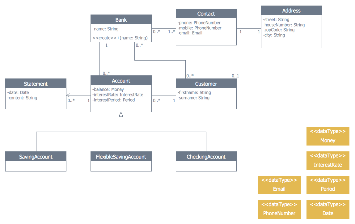
Picture: Banking System
Related Solution:
The Best Flowchart Software Available →
ConceptDraw gives the ability to draw Flowchart documents. Flowcharts solutionis a powerful tool that extends ConceptDraw application for drawing business flowcharts. ConceptDraw DIAGRAM vector diagramming and business graphics software enhanced with with templates, green and interactive flowchart makers, samples and stencil libraries from ConceptDraw Solution Park which all focused to help with drawing flowcharts, block diagrams, bar charts, histograms, pie charts, divided bar diagrams, line graphs, area charts, scatter plots, circular arrows diagrams, Venn diagrams, bubble diagrams, concept maps, and others. 
Picture: The Best Flowchart Software Available
Related Solution:
Flowchart Programming Project. Flowchart Examples →
Flowcharts can be used in designing and documenting both simple and complex processes or programs and, similar to the other types of diagrams, they can help visualize what happens and so help understand some definite process, and, as a result, find flaws, bottlenecks and other features within it. 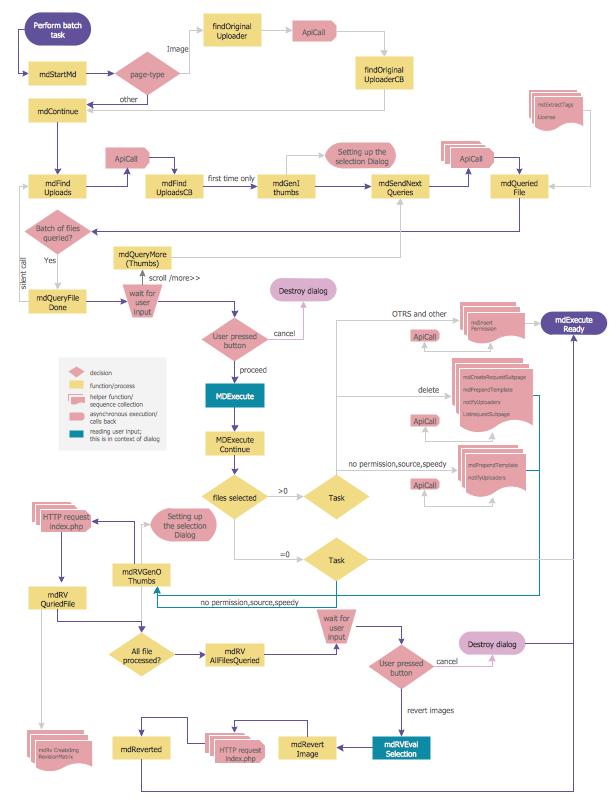
Picture: Flowchart Programming Project. Flowchart Examples
Related Solution:
How to create a UML Diagram →
ConceptDraw DIAGRAM extended with the Rapid UML solution is perfect for drawing professional UML diagrams. 
Picture: How to create a UML Diagram
Related Solution:
Entity Relationship Diagram - ERD - Software for Design Crows Foot ER Diagrams →
There are many ways to describe a database structure. One of the most usual is to draw an entity relationship diagram (ERD) using a Crow's Foot notation to represent database elements. If you don't want to draw it on paper, you should use an appropriate software. An entity-relationship (ER) diagram is used to show the structure of a business database. ERD represents data as objects (entities) that are connected with standard relationships symbols which Illustrate an association between entities. ERD, there is a wide range of ERD notations used by data bases architects for reflecting the relationships between the data entities. According to the crow's foot notation relationships are drawn as single labeled lines designating a certain kinds of relationship. Crow foot notation is a most frequently used ERD standard, because of improved readability of diagrams, with a more accurate use of space on the page. _Win_Mac.png)
Picture: Entity Relationship Diagram - ERD - Software for Design Crows Foot ER Diagrams
Related Solution:
Source: https://www.conceptdraw.com/How-To-Guide/uml-timing-diagram
Posted by: generousrendasays.blogspot.com

Posting Komentar untuk "Uml Timing Diagram Online Tool"